
Hydraulic cylinders, as the core actuating components in hydraulic systems, are responsible for efficiently converting hydraulic energy into mechanical energy to achieve linear reciprocating motion or oscillating motion. With their simple structure and stable performance, they are widely used in hydraulic systems of various types of machinery. They can drive reciprocating motion without the need for reduction devices, and their smooth, gap-free movement ensures efficient and precise transmission.
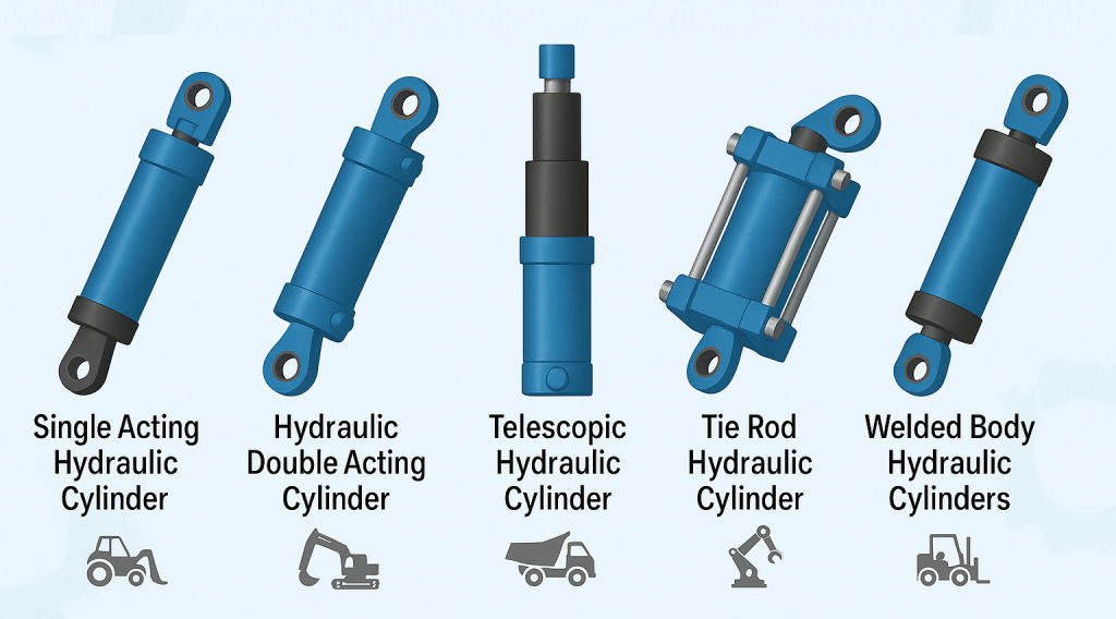
The output force of a hydraulic cylinder is directly proportional to the effective area of the piston and the pressure difference across its two ends. The main structure of a hydraulic cylinder includes the cylinder barrel, cylinder head, piston, and piston rod, equipped with sealing devices to ensure system tightness. Additionally, depending on actual usage requirements, buffer devices and exhaust devices may also be installed to ensure stable performance of the hydraulic cylinder in different application scenarios.
Detailed Composition of Hydraulic Cylinders ▼
Hydraulic cylinders are mainly composed of core components such as the rear end cover, cylinder barrel, piston rod, piston assembly, and front end cover. To prevent oil leakage or flow from the high-pressure chamber to the low-pressure chamber, sealing devices are carefully installed between the cylinder barrel and end covers, between the piston and piston rod, between the piston and cylinder barrel, and between the piston rod and front end cover. Meanwhile, to prevent the piston from striking the cylinder head during rapid return strokes, buffer devices are specially installed at the ends of hydraulic cylinders. Furthermore, exhaust devices may also be equipped as needed to ensure excellent stability and durability of the hydraulic cylinder in various application scenarios.
▲ Common Hydraulic Cylinder Structure Diagram
The cylinder barrel, as the core component of the hydraulic cylinder, together with the cylinder head, piston, etc., forms a sealed chamber that drives the piston to move. The cylinder head is mounted at both ends of the hydraulic cylinder, closely combined with the cylinder barrel to form the oil chamber. Its connection methods are diverse, including welding, threading, bolting, retaining keys, and tie rods. The selection needs to comprehensively consider factors such as working pressure, cylinder connection method, and usage environment. The piston rod, as a key component for transmitting force, is usually made of medium carbon steel (such as 45号钢). During operation, the piston rod may be subjected to thrust, tension, or bending moments, so ensuring its strength is crucial. At the same time, the piston rod slides in the guide sleeve, so the fit tightness also needs to be appropriate. The piston is an important component that converts hydraulic energy into mechanical energy. Its effective working area directly affects the force and movement speed of the hydraulic cylinder. The connection methods between the piston and piston rod also have various options, such as circlip type, bushing type, and nut type, which can be selected according to actual needs.
▲ Guide Sleeve
The guide sleeve plays a vital role in the hydraulic cylinder. It not only provides precise guidance and stable support for the piston rod but also requires high fitting accuracy, low friction resistance, and excellent wear resistance. Additionally, the sealing device inside the guide sleeve ensures the sealing performance of the rod side chamber of the cylinder barrel, while the external wiper seal effectively prevents impurities, dust, and moisture from entering, thereby protecting the sealing device and extending the service life of the hydraulic cylinder.
▲ Buffer Device
When the piston and piston rod are driven by hydraulic pressure at high speed and collide with the end covers and cylinder bottom of the oil cylinder, significant impact pressure and noise are generated. To solve this problem, buffer devices are introduced. Their working principle is to convert the kinetic energy of the oil in the low-pressure chamber of the cylinder barrel into heat energy through throttling, which is then carried away by the circulating oil. Buffer devices are divided into two types: constant throttling area and variable throttling structures, which can be selected according to actual needs.
▲ Hydraulic Transmission Principle
Hydraulic transmission uses oil as the working medium, achieves motion transmission through changes in sealed volume, and utilizes the internal pressure of the oil to drive working mechanisms. It consists of four parts: power, actuation, control, and auxiliary. The power part is responsible for converting the mechanical energy of the prime mover into the pressure energy of the oil; the actuation part converts the pressure energy of the oil input by the hydraulic pump into mechanical energy to drive the movement of the working mechanism; the control part is responsible for precisely controlling and regulating the pressure, flow rate, and flow direction of the oil; and the auxiliary part is responsible for connecting these core components into a complete system and providing necessary functions such as oil storage, filtration, measurement, and sealing.
▲ Structural Classification of Hydraulic Cylinders
Hydraulic cylinders, as the core actuating components in hydraulic systems, have diverse structures and can be classified into various types according to different standards. Among them, common structural classifications include: single-rod hydraulic cylinders, double-rod hydraulic cylinders, telescopic hydraulic cylinders, etc. These different types of hydraulic cylinders each have their unique roles and advantages in applications, providing a wide range of choices for the flexible application of hydraulic systems.
Piston-type hydraulic cylinders, especially single-rod hydraulic cylinders, are known for their unique structure. This type of hydraulic cylinder has a piston rod only at one end, and both ends are equipped with inlet/outlet oil ports A and B. These ports can simultaneously admit pressure oil or return oil, giving the hydraulic cylinder the ability for bidirectional movement, hence they are called double-acting cylinders.
Telescopic hydraulic cylinders are unique in having two or more stages of pistons. During extension, the pistons extend in order from large to small, while when retracting under no-load conditions, the order is usually from small to large. This design allows telescopic cylinders to achieve the long strokes required on construction machinery and agricultural machinery, while their length is significantly reduced when retracted, making the structure more compact.
Oscillating hydraulic cylinders, as actuating components that can output torque and achieve reciprocating motion, are also called oscillating hydraulic motors. They include single-vane and double-vane designs. In this cylinder, the stator block remains fixed, while the vanes are connected to the rotor. By changing the oil inlet direction, the vanes drive the rotor to perform reciprocating oscillations.
Main Parameters of Hydraulic Cylinders
Hydraulic cylinders have numerous key parameters, such as pressure, flow rate, size specifications, piston stroke, movement speed, thrust/pull force, efficiency, and hydraulic cylinder power. Among them, pressure, as the pressure exerted by the oil per unit area, is calculated by the formula p=F/A, which is the ratio of the load on the piston to the effective working area of the piston. On the same effective working area, an increase in load leads to a corresponding increase in the pressure required to overcome the load.
Furthermore, the service pressure of the hydraulic cylinder is an important basis for selecting its specifications. Common hydraulic cylinder specifications include: low-pressure hydraulic cylinders at 70 kgf/cm² (7 MPa), medium-pressure hydraulic cylinders at 140 kgf/cm² (14 MPa), and high-pressure hydraulic cylinders at 210 kgf/cm² (21 MPa).
Flow Rate: Flow rate describes the volume of oil passing through the effective cross-sectional area of the hydraulic cylinder barrel per unit time. It is calculated by the formula Q=V/t=vA, where V represents the volume of oil consumed by the hydraulic cylinder piston in one stroke, t is the time required for the piston to complete one stroke, v represents the movement speed of the piston rod, and A refers to the effective working area of the piston.
Piston Stroke: Piston stroke refers to the distance traveled by the piston from one extreme to the other during reciprocating motion. In practical applications, standard strokes close to the actual working stroke are usually selected under the premise of meeting the stability requirements of the oil cylinder.
Piston Movement Speed: The piston movement speed, i.e., the distance the pressure oil pushes the piston per unit time, is calculated by the formula v=Q/A.
Size Specifications: The size specifications of hydraulic cylinders include the inner and outer diameters of the cylinder barrel, piston diameter, piston rod diameter, and cylinder head dimensions, etc. Determining these dimensions requires comprehensive consideration of factors such as the usage environment of the hydraulic cylinder, installation method, required thrust/pull force, and stroke.
Internal Structure Design of Hydraulic Cylinders
Design Principles: Calculate the dimensions of the internal structure accurately based on the actual working temperature, the working medium used, and the factory’s processing capability, referring to the mechanical design handbook.
The selection of seals should comprehensively consider the onsite working temperature, environmental pollution conditions, and the characteristics of the working medium. Special attention should be paid to the fact that polyurethane seals are not suitable for water-glycol media.
For the design of the cylinder head, the use of V-type combination seals is recommended, as this design can effectively compensate for surface finish errors in groove machining.
The dimensions of the seal groove must be precisely calculated and designed strictly according to the design handbook to ensure sealing effectiveness.
For sealing the cylinder piston, Glyd rings combined with guide strips are usually selected. Glyd rings are highly regarded for their excellent high-temperature resistance and pollution resistance.
For selecting cylinder seals, the Japanese NOK series is usually recommended. The use of domestic oil cylinder seals should be avoided to ensure smooth cylinder starting and stable operation.
To enhance the sealing effect of the O-rings between the cylinder head, cylinder bottom, and cylinder barrel, it is recommended to add backup rings, which can effectively compensate for machining errors.
When connecting the cylinder barrel to the cylinder head, cylinder bottom, and central mount, the use of welding should be avoided as much as possible because welding may cause deformation of the cylinder barrel. Threaded connections or other suitable connection methods are recommended.
Hydraulic Cylinder Oil Leakage
External leakage, where oil leaks from various improperly sealed areas of the hydraulic cylinder to the external atmosphere, is a common problem with hydraulic cylinders. The following are three main cases of external leakage and their solutions:
(1) Oil leakage occurs at the sealing area between the cylinder sleeve and cylinder head (or guide sleeve). In this case, usually replacing the O-ring solves the problem.
(2) Oil leaks outward during the relative movement between the piston rod and the guide sleeve surface. This may be caused by piston rod damage or guide sleeve wear. For piston rod damage, try cleaning it with gasoline, applying metal adhesive, and scraping off the excess; if the guide sleeve is worn, it needs to be replaced with one that has a slightly smaller inner diameter.
(3) Poor sealing of hydraulic cylinder pipe joints can also cause oil leakage. When dealing with such problems, in addition to checking the sealing condition of the seals, it is also necessary to ensure that the joints are correctly assembled, reliably tightened, and the contact surfaces are free of scratches. Replace or repair if necessary.
Internal Leakage in Hydraulic Cylinders
Internal leakage in hydraulic cylinders refers to the phenomenon where oil flows from the high-pressure chamber to the low-pressure chamber through various clearances inside the hydraulic cylinder. Since internal leakage is relatively hidden and usually not directly observable, it can be judged through the system’s working conditions, such as insufficient thrust, decreased speed, unstable operation, or abnormal oil temperature rise. Internal leakage generally occurs at the following two locations:
(1) The static sealing area between the piston rod and piston. To address this issue, O-rings can be added to the sealing surfaces of both to enhance the sealing effect.
(2) The dynamic sealing part between the cylinder sleeve inner wall and the piston. When internal leakage is detected, a detailed inspection of each fitting part should be conducted first. The cylinder sleeve is often repaired by boring the inner hole, followed by fitting a piston with an increased diameter to restore sealing performance.